 LYNXSPACE
Project · Test bench
WINDTUNNEL
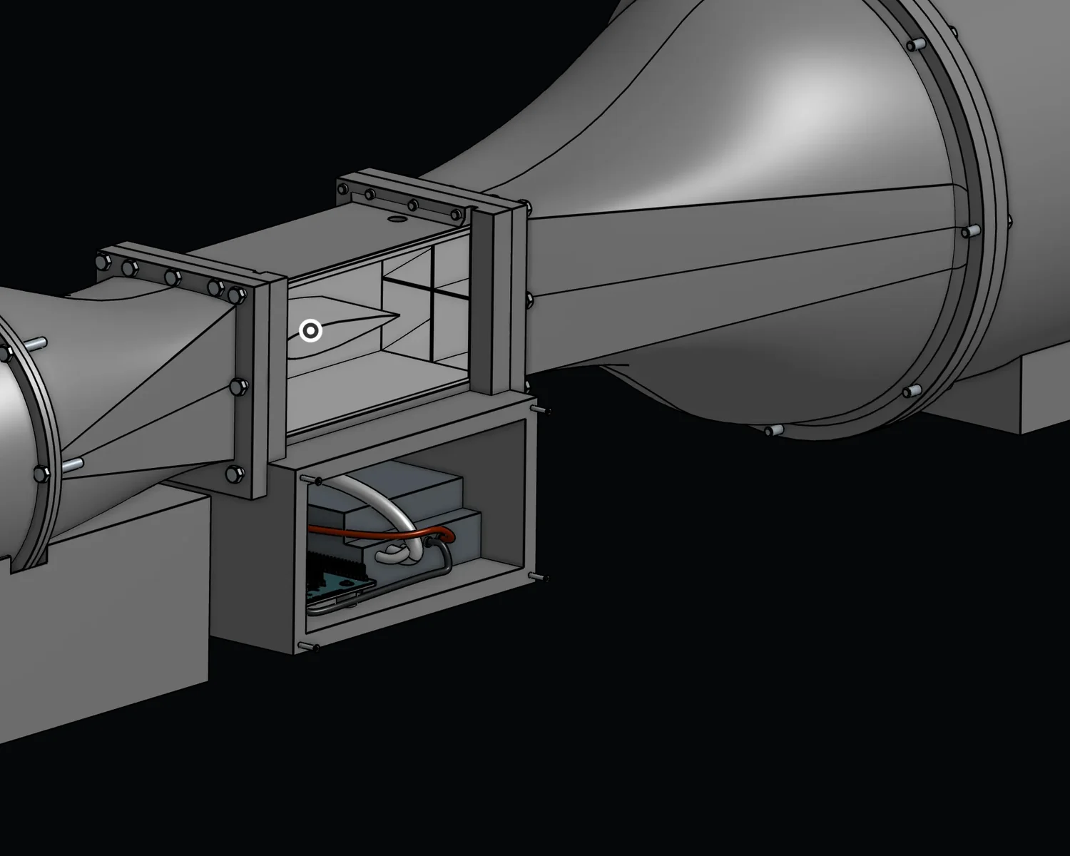
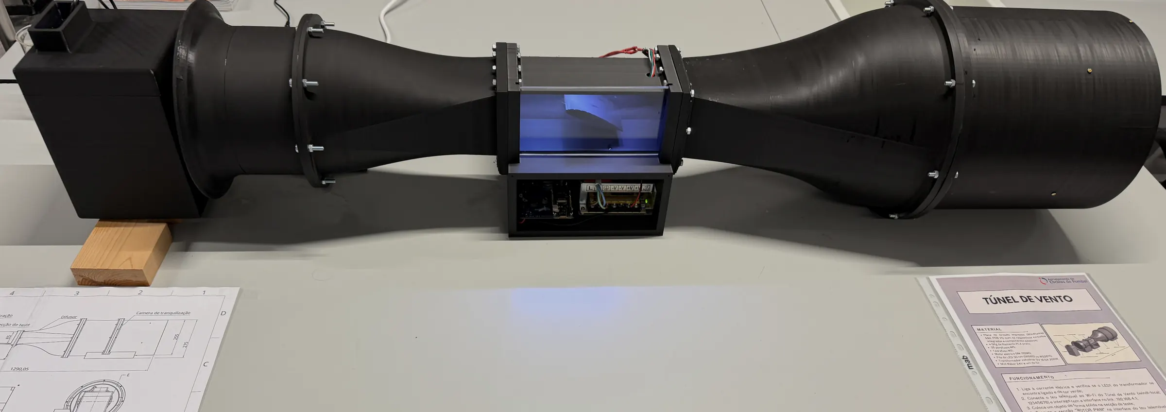
Bench-scale wind tunnel for flow visualisation, built for teaching and demonstration. A 1.29 m duct with a bellmouth intake, run from custom boards.
| Type | Bench wind tunnel |
|---|---|
| Intake | Bellmouth |
| Visualisation | Vapour trails |
| Control | Onboard web server |
| Mass | Not yet measured |
| Stage | Ready for demonstrations |
- Test section
- 70 × 200mm
- Overall length
- 1.29m
- Diffuser exit
- 255mm
- Flow range
- 10–40km/h
Project
Vapour trails at 10–40 km/h
Everything on this bench serves one job: making the flow visible inside a 70 × 200 mm working section.
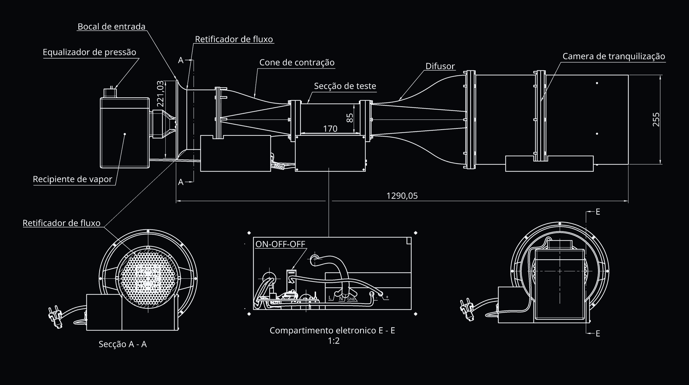
Air enters through a 221 mm bellmouth intake, passes a honeycomb flow straightener and a contraction cone, and reaches the 70 × 200 mm working section, which has a 170 × 85 mm window to watch through. A diffuser then opens the duct back out to 255 mm. A 5 V mist maker feeds vapour into the stream and an addressable LED strip lights the section, so the trails read against the background. Speed through the section is measured with a pitot tube.
Control is a web server running on the tunnel's own boards, so it is driven from a phone or a laptop on the same network rather than from a dedicated console. The electronics are custom PCBs. The assembly is modular: the bolted flanges between sections mean one section can be changed without rebuilding the tunnel.
Reference sheet
WindTunnel dimensions and systems
| Test section | 70 × 200 mm |
|---|---|
| Viewing window | 170 × 85 mm |
| Overall length | 1.29 m |
| Inlet diameter | 221 mm, bellmouth |
| Largest diameter | 255 mm, at the diffuser exit |
| Mass | Not yet measured |
| Flow range | 10–40 km/h |
|---|---|
| Measured with | Pitot tube |
| Visualisation | Vapour trails, 5 V mist maker |
| Lighting | Addressable LED strip |
| Control | Onboard web server |
|---|---|
| Boards | Custom PCBs |
| Construction | Modular, bolted flanges |
| Power draw | Not yet measured |
Mass and power draw are the two figures this bench has never had put to it, so they are marked rather than filled in. Everything else above is dimensioned on the general arrangement below. Two readings worth naming: the 170 and 85 marked across the test section are its viewing window, not the section itself, and the bellmouth is drawn at 221,03, published here as 221 mm.
Contact
What you can run in it
The working section is 70 × 200 mm and the assembly is modular, so a section can be changed for a different profile. If you teach fluid mechanics, or you need a particular flow made visible, tell us what you need to see.